This is the software, which runs the Pecan Pico 7 balloon trackers. Since the new trackers can be used in many ways, this software is designed to be multiple purpose. It can be used for:
- Image transmissions
- Position/Telemetry transmission (GPS)
- by APRS AFSK or 2GFSK
- 2FSK (RTTY)
- CW (morse)
This software may also provide in feature
- Amateur satellite communication links
- Full duplex relay for digital modulations (up 70cm, down 2m)
- Ground control access by radio link
These are some images which were transmitted by SSDV. These QVGA-images were shot by an Omnivision OV9655.

Currently there is only one target which is supported by the Software. Pecan Pico 7a will be replaced by Pecan Pico 7b due to some mayor errors (See known PCB errors).
All features can be combined as it's needed for the user. Currently this software if unfinished but basic features can be used:
- Image capturing (just QVGA at the moment) and transmission by SSDV
- Receiving positions (by ublox MAX8 GNSS module)
- Measuring Temperature/Airpressure/Temperature (by onboard BME280)
- Measuring external Temperature/Airpressure/Temperature (by external BME280)
- Measuring power consumption (battery charging and discharging)
- Position and telemetry transmissions by 2FSK (or RTTY)
- High altitude mode (up to 50km altitude)
- Debugging (serial connection)
- APRS encoding (AFSK)
What currently doesn't work at the moment (but planned):
- APRS encoding (2GFSK)
- High resolution image capturing (just QVGA at the moment)
- High resolution image transmissions by 2GFSK 9k6 APRS
- Logging and Log transmissions
- Amateur satellite orbit calculations and transmissions
- Power save modes
- Store data on the microSD card
- 9-axsis sensor driver (MPU9250)
It is currently not planned to implement video capturing. The STM32F4 doesn't have enough calculation power for compression encoding. However the new pin-compabile STM32F7x7 supports JPEG encoding. So video capturing may be possible in future.
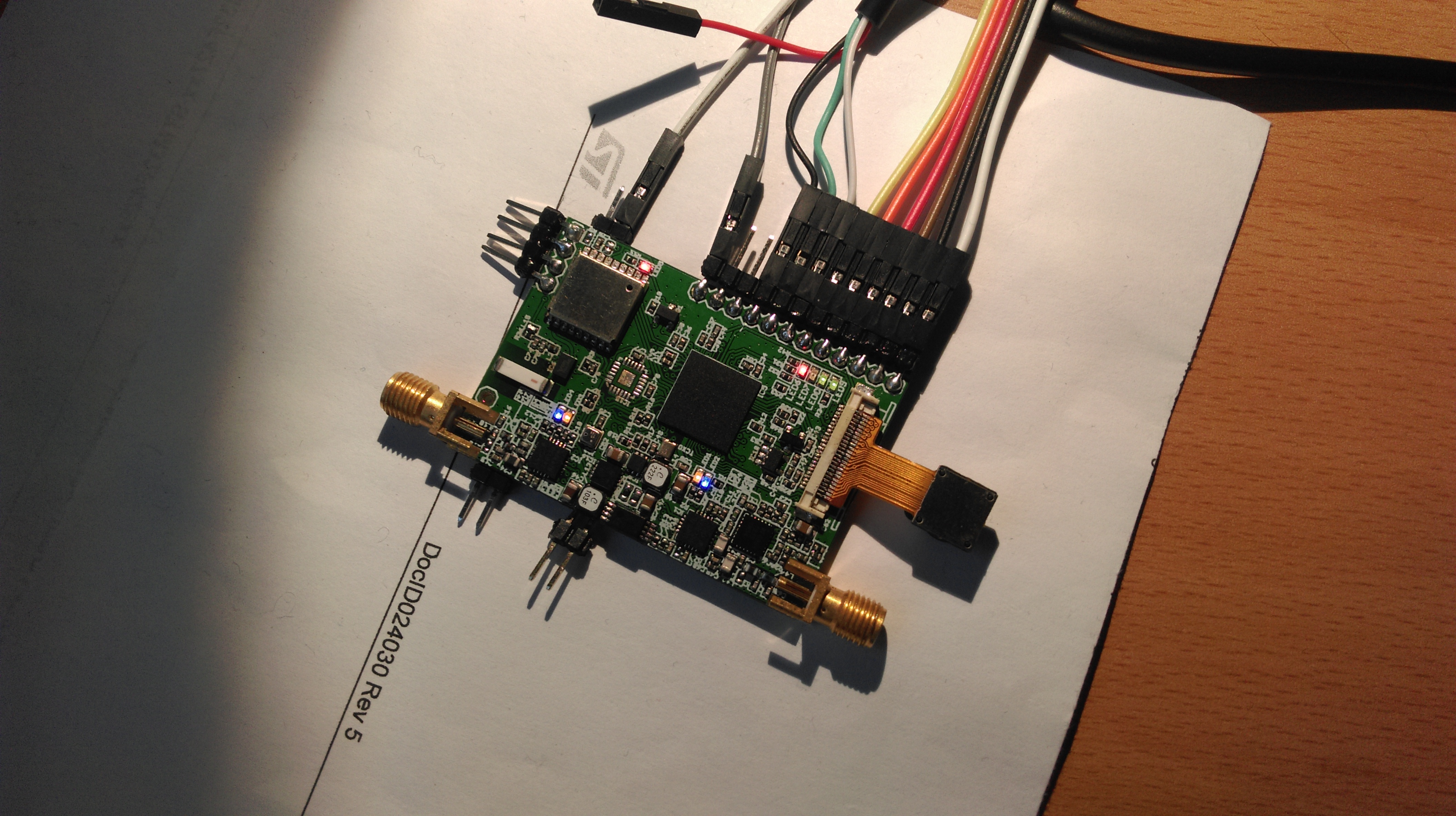
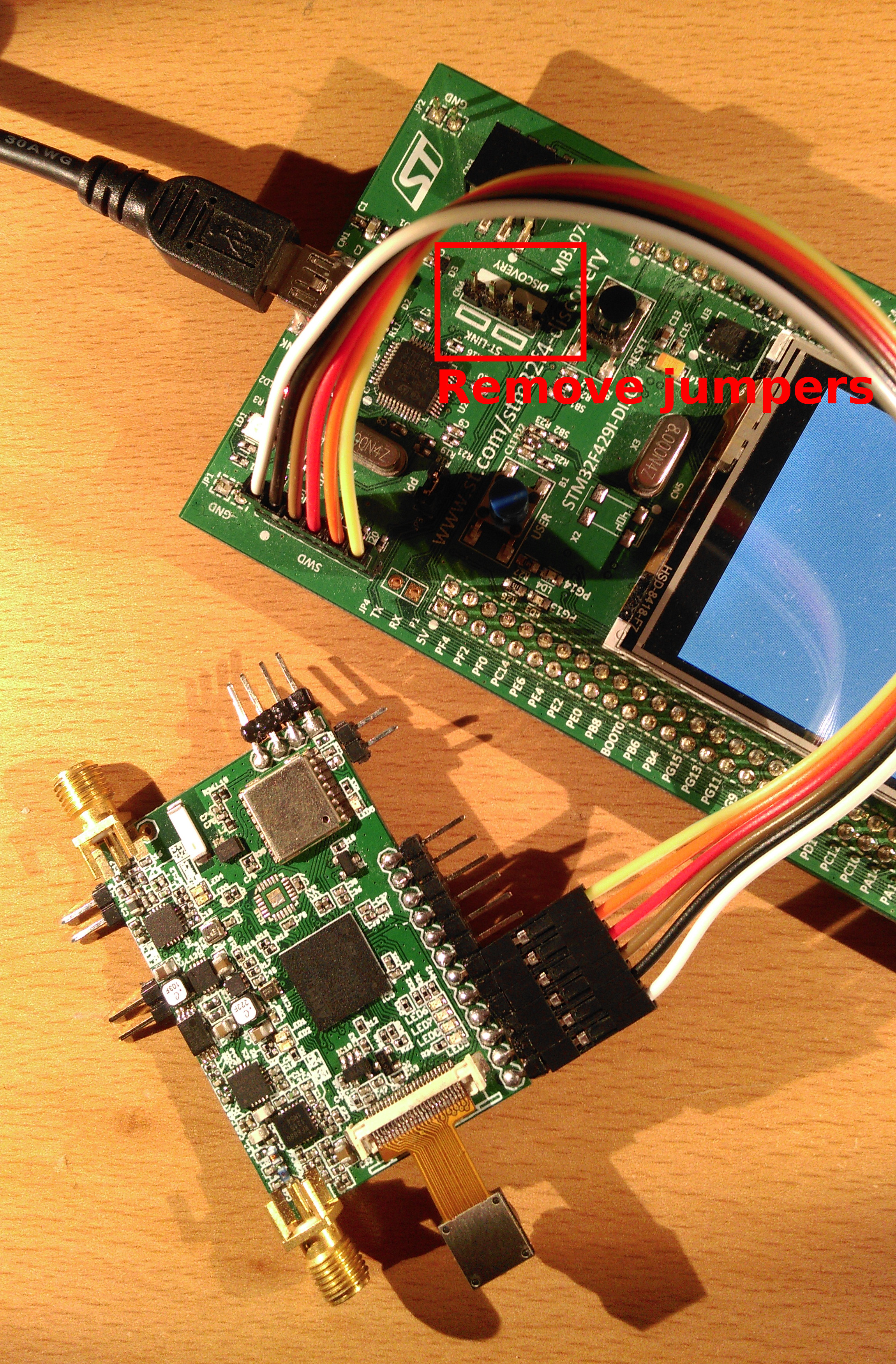
In order to make the hardware working, you are going to need a programmer. There are several devices on the market but I personally use the STM32F429I-DISCOVERY demo board. The discovery board is basically a programmer with a demo target (microcontroller) attached to it. It's designed in a way so you can either flash the demo target or the Pecan Pico 7 by switching specific jumpers on the board. You may get the programmer on Mouser, Farnell, Digikey or on Ebay for roughly $30. You need to connect the programmer following way. Don't forget to remove the jumpers which connect the programmer with the demo target.
You will also need some software dependencies.
- GCC to build binary files
- ST-Flash to flash the binaries to your target There's a great guide on the Web which I've taken myself to set up everything. They are using a different demo board but it works the same.
Then you are going to need the sources for the tracker:
git clone --recursive https://github.com/DL7AD/pecan-stm32f429.git
cd pecan-stm32f429
make
make flash
A build folder will be created automatically. The software can be additionally configured in the config.h.
Technical description below...
This section describes the different function blocks in the software and how they interact which each other. The software provides multiple modules, which supply the main functionality of the tracker like transmitting positions or images. Modules are basically threads in the ChibiOS RTOS. Modules can be:
- POSITION - for transmining position and telemetry
- IMAGE - for transmitting images
- LOG - for transmitting logs
There are two more specific modules which are started automatically be the software itself. They are necessary to do input/output jobs.
- TRACKING (or tracking manager) - collects all the data from the peripheral components (BME280, GPS, etc.) and provides them (as struct) to other modules in the software.
- RADIO - provides the two radios which are available. This module receives internal messages by other modules which want to send packets via VHF or UHF.
The following diagram shows how the modules interact with each other.
   DRIVER   |                  DATA PROCESSING MODULES                     |     DRIVER
------------+--------------------------------------------------------------+------------------

 MPU9250 ---+                           +---> SATELLITE ---+
            |                           |                  |
 BME280 ----+---> TRACKING Manager -----+---> POSITION ----+----> RADIO ---+---> RADIO1 (2m)
            |                           |                  |               |
 MAX -------+                           +-----> LOG -------+               +---> RADIO2 (70cm)
                                                           |
 OV9655 or ----------------------------------> IMAGE ------+
 OV2640
In order to use these modules, they can be configured operational in the MOULDES() macro in the configuration file. All modules can be configured except of TRACKING and RADIO. They must not be configured because they are launched by the software automatically. The following example shows how a image module and a position module can be configured.
MODULES() { \
    MODULE_IMAGE   (TX_CONTINUOSLY,          SLEEP_WHEN_BATT_BELOW_3V5, CUSTOM_FREQ, 10, PROT_SSDV_2FSK ); \
    MODULE_POSITION(WAIT_FOR_TRACKING_POINT, SLEEP_WHEN_BATT_BELOW_3V0, CUSTOM_FREQ, 10, PROT_UKHAS_2FSK); \
}
As you can see, there are some parameters which can be used to configure a specific module:
Parameter 1 specifies in which cycle the modules shall send it's data. This may be an amount of seconds. It's also allowed to place TX_CONTINUOSLY or WAIT_FOR_TRACKING_POINT in this field.
TX_CONTINUOSLY - Transmit new data once the old it sent completely
WAIT_FOR_TRACKING_POINT - Transmit when tracking manager generates a new track point
Parameter 2 specifies the sleep mode. Note this functionality is currently not implemented. The modules will disregard this field.
Parameter 3 specifies a frequency method. Currently CUSTOM_FREQ or APRS_REGION_FREQ can be used. The frequencies are currently static and set in radio.c. CUSTOM_FREQ is set to 434.500MHz and APRS_REGION_FREQ is set to 144.800MHz. It's planned to implement a geofencing algorithm in the future for APRS_REGION_FREQ in order to find out the specific APRS region frequency by the actual location.
Parameter 4 specifies the transmission power in dBm. If the value is set to a point which the radio is unable to do (or damaging the PCB) the actual value may be limited by the RADIO module.
Parameter 5 specifies the protocol and modulation. While you can use PROT_UKHAS_2FSK, PROT_APRS_AFSK or PROT_RAW_CW for the POSITION module the IMAGE module can only accept PROT_SSDV_2FSK at the moment.
Note not all of the parameter call be used for all individual modules because some configurations may not make sense e.g. CW modulation for transmitting images. You can find an exact documentation in the configuration file which specific parameters can be applied to the the modules.
Modules can be combined various combination. But modules can be also understand as classes which instances can be used multiple times. So if you want to transmit telemetry and positions by RTTY and APRS at the same time, you may configure modules multiple times. The following example shows, how the position/telemetry is sent on a custon frequency while it's also transmitted by APRS on the regional APRS frequency and CW.
MODULES() { \
    MODULE_POSITION (WAIT_FOR_TRACKING_POINT, SLEEP_WHEN_BATT_BELOW_2V5, CUSTOM_FREQ,      10, PROT_UKHAS_2FSK); \
    MODULE_POSITION (WAIT_FOR_TRACKING_POINT, SLEEP_WHEN_BATT_BELOW_2V5, APRS_REGION_FREQ, 10, PROT_APRS_AFSK ); \
    MODULE_POSITION (WAIT_FOR_TRACKING_POINT, SLEEP_WHEN_BATT_BELOW_3V0,CUSTOM_FREQ,       10, PROT_RAW_CW    ); \
}
The tracking manager keeps an eye on all peripheral components which provide data. With exception of the camera, the tracking manager collects the data of:
- BME280 (airpressure, humidity, temperature)
- MAX7/8 (GPS/GLONASS receiver)
- PAC1720 (Power consumption tracking) The data of these components will be collected in a specific cycle time and provided to other modules in a struct trackPoint_t. The most recent sampled data can be accessed by other modules by getLastTrackPoint().
The module RADIO handles the two radios which are available on the Pecan Pico 7. It initializes a mailbox in which messages (or data packets) can be written by other functions in order to use the radios. If a module wants to send a packet on HF, it may generate a radioMSG_t struct and pass is over to transmitOnRadio(). The radio will determine a suitable radio by the frequency which is set in the struct. Once the radio is not used, the module will send the message. If the radio is already in use, the RADIO module may buffer up to 3 more messages in a message queue. The queue is cleared by the FIFO concept. While only 3 messages can be stored in the queue, the maximum generation-transmission delay is quiet small (<15sec usually). transmitOnRadio() may return true if the message is sent to the queue. False indicates the queue is full. If a module wants to send the message, it has to try again by calling transmitOnRadio() again. While there is no priority management at the moment, the modules have to try more or less aggressivly to insert its messages to the radio queue. This strategy more a workaround than a solution. Priority management would be better.
The APRS modulation is a Si446x-specific hack.
This modulation is currently not supported. Well... it is. It just doesnt work at the moment.
This module handles the radio transmission encoding for all position/telemetry packets. It is able to encode CW, APRS and 2FSK (or RTTY). A cycle can be continuosly, time-specific or be triggered by the TRACKING manager when a new track point is published. This modules can be configured in the MODULES() marco: MODULE_POSITION(trigger, sleep, frequency, power, protocol).
| Field | Meaning | Possible options |
|---|---|---|
| trigger | Cycle time or trigger type for transmission | TX_CONTINUOSLY or WAIT_FOR_TRACKING_POINT or Integer (in seconds) |
| sleep | Sleep method | SLEEP_WHEN_BATT_BELOW_2V9 or SLEEP_WHEN_BATT_BELOW_3V0 ... SLEEP_WHEN_BATT_BELOW_4V1 or SLEEP_WHEN_ISS_NOT_VISIBLE |
| frequency | Frequency method | CUSTOM_FREQ or APRS_REGION_FREQ or APRS_ISS_FREQ |
| power | Radio power (in dBm) | Integer |
| protocol | Protocol | PROT_APRS_2GFSK or PROT_APRS_AFSK or PROT_UKHAS_2FSK or PROT_RAW_CW or PROT_APRSCONFIG_AFSK or PROT_APRSCONFIG_2GFSK |
For a detailed explanation about the option macros see config.h.
This software makes use of the amateur radio APRS system (Automatic Packet Reporting system), which has been invented by Bob Bruninga in 1992. Since APRS has a great coverage in the US and Europe, is it very useful for balloon tracking. At the moment its also the most convenient system which can be used.
The software itself implements the compressed format. This software is actually not recommended but supported by all devices. Since there has been no replacement and the raw format is quiet big, this is still the best encoding option. The format also supports 5 different 13bit-telemetry transmissons which are used for:
- Battery voltage
- Solar voltage
- Temperature (in Celcius)
- GPS Satellites
- TTFF (time to first fix)
The software also might display a GPS-LOSS counter in the comment field. If GPS can be received the comment field may be empty. Note the telemetry fields are mathematically encoded and the receives have to know, how they can decode this telemetry. In order to transmit the configuration by the tracker itself, place a POSITION modules in the MODULES() marco in the config.h. It will transmit all the necessary information for the receiver.
MODULE_POSITION (3600, SLEEP_WHEN_BATT_BELOW_3V0, APRS_REGION_FREQ, 10, PROT_APRSCONFIG_AFSK);
All APRS messages will be encoded by the POSITION module for the RADIO module in a bitstream (1 bit = 1 Symbol). The packets already contain the AX.25 specific bitstuffing and scrambling (for 2GFSK).
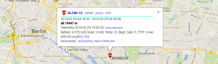
Transmitted APRS packet displayed by APRS.fi
2FSK messages will be encoded especially for the UKHAS system. Unlike AFSK, this modulation can be only received with a SSB receiver. See on the UKHAS Tracking Guide which receivers can be used. While UKHAS is very flexible, the packet format can be configured in the configuration file by the UKHAS_FORMAT marco. The format contains a set of variables which can be changed user specific.
#define UKHAS_FORMAT "<CALL>,<ID>,<TIME>,<LAT>,<LON>,<ALT>,<SATS>,<TTFF>,<VBAT>,<VSOL>,<CHARGE>,<IPRESS>,<ITEMP>,<IHUM>,<EPRESS>,<ETEMP>,<EHUM>"
The snychronisation ($$$$$) in the front and CRC calculation at the end will be added by the software automatically. The output could be:
$$$$$D-9,5,00:03:15,52.4999910,13.5000084,19948,9,16,4.33,0.00,-1.114,100271,36.1,22,0,0.0,0*8B0B
| Data | Explanation |
|---|---|
| $$$$$ | Snchronisation (added by the software) |
| D-9, | Payload name (See UKHAS_CALLSIGN info config.h) |
| 5, | Sequence ID (incremented each TRACKING manager cycle) |
| 00:03:15, | GPS Time (when this fix has been sampled) |
| 52.4999910, | GPS Latitude |
| 13.5000084, | GPS Longitude |
| 19948, | GPS altitude in meters |
| 9, | GPS satellites |
| 16, | TTFF (in seconds) |
| 4.33, | Battery voltage (in volts) |
| 0.00, | Solar voltage (in volts) |
| -1.114, | Power consumption (in Watts) |
| 100271, | Air Pressure of onbard BME280 (in Pascal) |
| 36.1, | Temperature (in Celcius) |
| 22, | Humidity (in %) |
| 0, | Air Pressure of offbard BME280 (in Pascal) |
| 0.0, | Temperature of offbard BME280 (in Celcius) |
| 0 | Humidity of offbard BME280 (in %) |
| *8B0B | CRC (Calculated by software) |
The CRC calculation uses crc16-ccitt (0x1021). A detailed documentation about the tags can be found in the config.h.
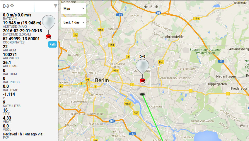
Transmitted 2FSK packet displayed by HABHUB
CW was implemented while some persons are not able to do APRS/2FSK or simply don't like it. Since no additional equipment is needed for decoding, the signal can be possibly picked up by someone else who don't know about the balloon launch and how to decode it. CW might be also useful for ARDF (Amateur radio direction finding) if the GPS failed to receive.
Like 2FSK, CW encoding can be configured flexible by the CW_FORMAT macro. All configuration tags which are known for 2FSK can be also used for CW. The POSITION module may encode A-Z, 0-9, "." and space. All other characters will be dismissed e.g. "D-9" => "D9". #define CW_FORMAT "<CALL> <LOC> <ALT>M PSE QSL" will encode a tracking point as D9 JO62RM 19948M PSE QSL. The message will be encoded binary as 1/10sec bitstream (1: Tone, 0: No Tone). This message is then sent to the RADIO module.
Note CW is no format which is very useful for computer-enabled processing, so there is no service like APRS.fi or the tracker service by HABHUB for CW.
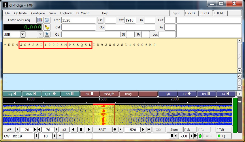
Transmitted CW message contains Maidenhead Locator and altitude displayed by DL-FLDigi
This software includes some other packages which I have used to make this project possible:
JPEG Ant - JPEG compression for microcontrollers
ChibiOS - Real time operating system (Source)
SSDV - Slow Scan Digital Video (Source)