##Prelab The prelab to this lab was very important, as without it you were very likely to end up burning fuses, motor driver chips, and even the MSP430 - not to mention the robot almost certainly wouldn't work.
###Wiring The first question I needed to ask myself from a hardware standpoint was what method I wanted to use to output the pulse width modulation signals (PWM) which would power the motors. The lab offers multiple possibilities, and before I decided on which one, I consulted the tech docs.
####The Motor Driver Chip The motor driver tech doc gives a schematic of the chip and a truth table. Here is the truth table for a single port:
| A | EN | Y |
|---|---|---|
| H | H | H |
| L | H | L |
| X | L | L |
Essentially, when enable is high, the output mirrors the input. This means that I could wire each input to a port on the MSP430 and each output to a terminal on the motor. The issue emerges when you start to think about going backwards. Misunderstanding the tech doc led me to believe that I could not apply an effectively negative voltage to the input; it must be either HIGH or LOW, which meant that I had to be very creative to run current the opposite direction through the DC motor in order to control direction.
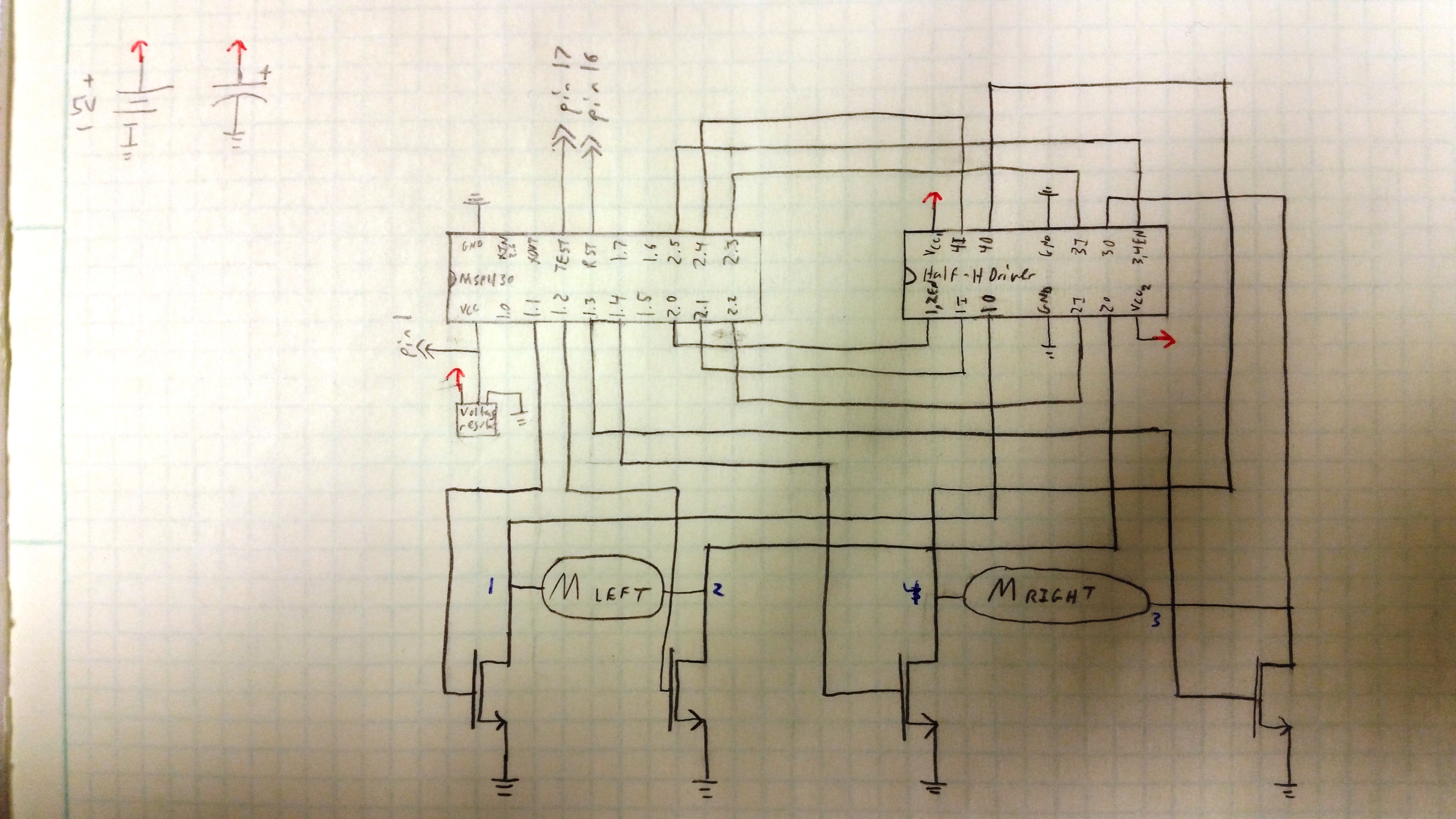
Here is the resulting schematic:

Let me just say, I was extremely excited about this masterpiece. The transistors are NMOS MOSFET transistors. BS-170, to be exact, with a threshold voltage of 2.1 volts, the 3.3 V output would have been enough to turn these on. This would have opened the correct path to ground, and this combined with toggling which PWM signal was being outputted, would have forced current to run through the motor the proper direction.
###Pseudocode Once I had my schematic drawn up, I had to begin thinking about how I would implement things. I wanted to make it efficient, so many of my controls would be done through #define statements and the rest would be controlled by calling the proper case for a switch. This can be seen in my pseudocode text file.
###The Reality As it turned out, this prelab was educational and very entertaining, but not ultimately how I built my circuit. First, the maximum continuous current for the BS-170 is 500 mA. This meant that I would be very limited to using only half of my robot's speed and power. Also, I did not understand the Timer A PWM functions. I thought that when the specified value was reached an interrupt was triggered, within which I would have to manually toggle the appropriate bits. On the contrary, using Set / Reset mode automatically SETS and RESETS the pin. Of course, the pin must be tied to the appropriate timer as well as configured to read off of it. But when I looked at Dr. Coulson’s code and heard that it alone would cause the robot to drive forward - given proper wiring - I was shocked.
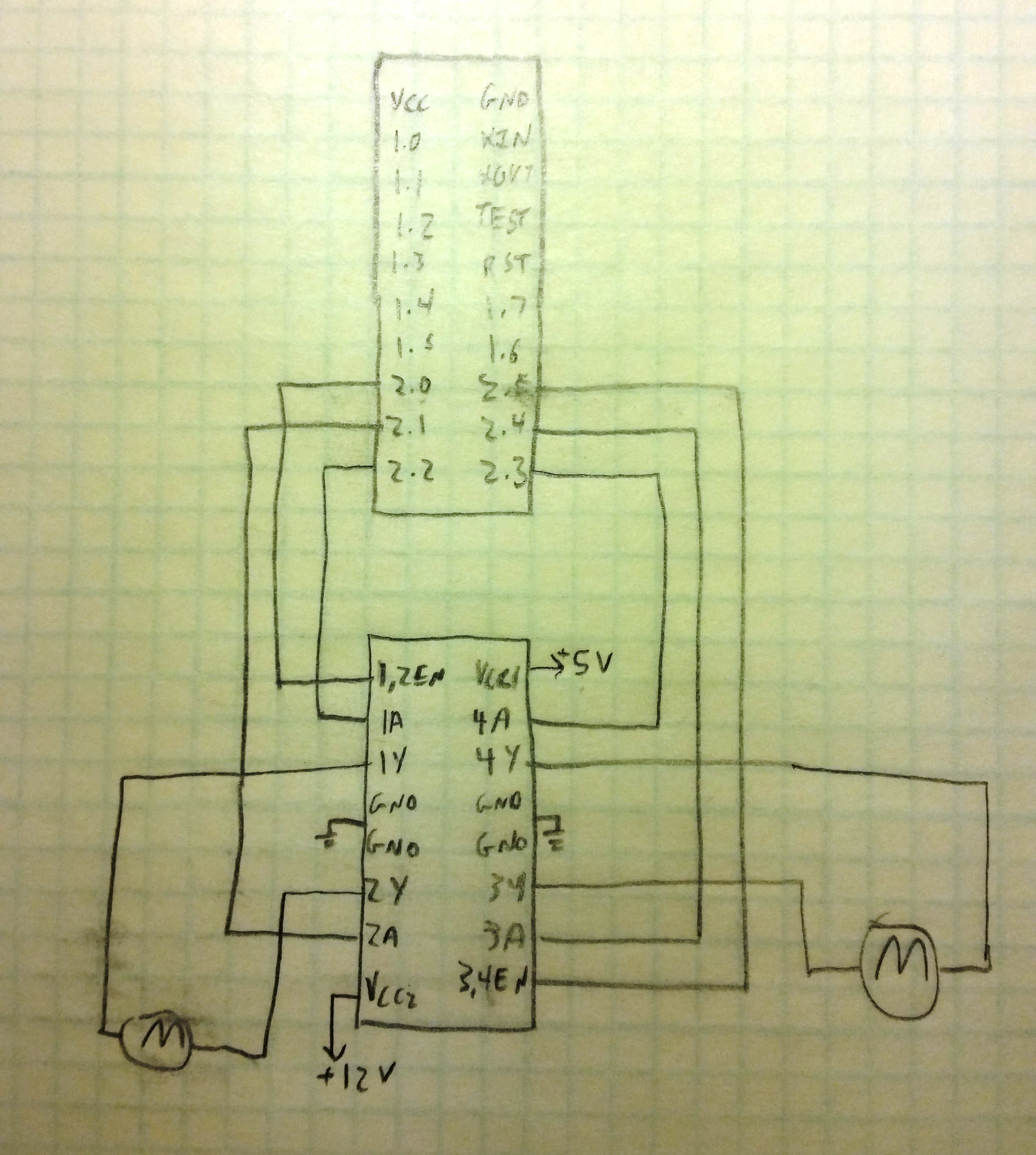
Furthermore, it turns out that a LOW output can be treated as a ground, so I didn't need transistors at all (though I still think they would have been AWESOME). This means that I could greatly simplify my schematic:
##Required Functionality This lab was a good combination of DIY and some helpful hints from the powers that be. I had some initial issues figuring out which power to connect to which VCC on the motor chip, but Sabin Park (they man, the myth, the legend) helped me out. I also was sure to include the noise reducing capacitors recommended by the instructors:
- Between the motor inputs and ground
- One electrolytic across each power supply
- Between the Reset pin and ground
Once I had this all worked out and wired properly, the given code ran the motors (though I changed them to both be Set / Reset). Sadly, it was not that simple. At one point I blew a 2 A fuse and my MSP430 by connecting the output 2A to the +12 V line. Be careful with your wires! I replaced the fuse, but didn't realize I had messed up my microcontroller until after a generous amount of unhappiness.
###The Code My pseudocode actually ended up being somewhat helpful: I embedded the given code within the program and then used my switch statement to toggle the appropriate bits and send the signals I wanted to the motors. I had to do a little guess and check with what I wanted my delay cycles to be, as for the "dance" that we did for required functionality, I called a method, then stopped the robot after a delay and proceeded with the next command. You can see this earlier commit here. In future labs I plan to make this better by adding in options to increase or decrease the duty cycle and thereby vary speed.
###The Pesky Reset While plugged in to the USB with the robot on blocks, the code worked very well. However, when I placed it on the ground, it would begin executing the program, then randomly stop and start again from the begging. This seemed to me like the robot was resetting. It seemed funky to me that we were relying on a little tiny capacitor to protect the "very sensitive to voltage fluctuation" reset pin, and sure enough, Captain Trimble recommended some more caps. So I increased the size of the electrolytic on the voltage supply lines and added one on the +3.3 V that was coming out of my voltage regulator. I also wired reset to HIGH instead of just a little capacitor. That did the trick!
##A Functionality The cool thing about this was that I already had all of the code written! Literally all I had to do was copy and paste things from Lab 5 and it worked. Ahh the sweet reward of good coding practices to begin with!
I simply copied the decoder code - namely, handlePress() - and some of the header file. Then, I replaced the lines that used to control the block on the LCD screen with a call to the void drive(direction) function and a bam. Of course, I did have to work on my initializations because using Timer A to reset the packetIndex conflicts with the PWM signals. I may try and find a nicer way to do this, but if we are done with the IR sensor than this method is still very functional.
##Documentation As mentioned, C2C Sabin Park was extremely helpful with the actual wiring of the motor driver chip.
