The FSS project has been moved to GitLab: https://gitlab.com/reds-public/fss. This repository will receive no further updates.
FSS is a system, developed at the REDS Institute, that interfaces QEmu (one of the most renowned machine emulators) with ModelSim/QuestaSim, two standard multi-language HDL simulation environments by Mentor Graphics.
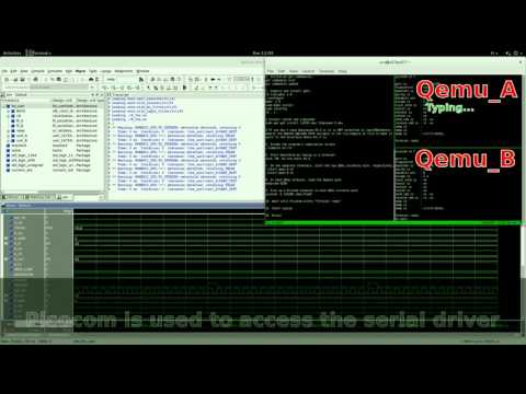
An example of its operation is shown in the figure below:

Traditionally, debugging the HDL requires writing a test bench, making assumptions on I/O, and then checking that these assumptions are satisfied by the given design. From the software side, instead, the code was developed according to a set of specifications listing the capabilities of the hardware counterpart and how to use them, and tested with a simulator that ideally matches these specifiecations. Predictably, when the two parts are interconnected, the slightest mismatch with respect to the specifications will result in errors, crashes, and unexpected behavior in general. When this happens, figuring out what is not working properly --- but even before that, in which part (HDL design? Software? Interface? Specifications?) --- is an extremely hard task.
With FSS, instead, the simulation can be driven directly by the real software part (in the example, the UART kernel's driver of the Linux distribution running inside the two QEmu instances).
This has several important advantages:
- the designer of the HDL part does not have to "forecast" its interactions with the software parts (saves time and avoids bugs in the interface)
- the HDL design is exposed to the real behaviour of the software, and not just to a set of specifications written on paper, easing the identification of the bugs (tests are more meaningful)
- even more importantly, the designer has full visibility on the system while it is interacting with the software, thus she has control on the visualized information, can alter or delay signals at wish, ... (designer has total control on the simulation)
In the considered example, running the simulation (given in the fss_demo_uart subdirectory) as explained in the INSTALL file, gives the result depicted by the figure below.

The following video shows the UART demo in execution:
Modern electronic devices are often heterogeneous in nature. This is due to the limitations imposed by the current technology that prevent us from pushing the clock rates beyond a certain limit, and thus motivates us to step back from general purpose processors and specialize the architecture to best fit the problem at hand.
In particular, it is not uncommon to see boards that couple an ARM processor with an FPGA. The former usually deals with standard operations, such as running an operating system and interfacing with the user, while the latter takes charge of the application-dependent tasks that can, in this way, take advantage of the huge parallelism it can offer. A notable example of such boards is represented by the recent Zynq SoC, but the acquisition of Altera by Intel supports the hypothesis that these architectures are going to become the new standard in the near future.
While the above mentioned strategy allows for impressive performance gains, the complexity of the overall system increases greatly: not only programming the two parts requires different skills (and thus the development is usually performed by two separate teams), but also the interactions between them are not easily defined, tested, and debugged. This fact makes the boundary between them one of the most critical points in the system design.
Despite well-defined best practices, the lack of appropriate tools makes it the norm to test the CPU software design using a set of test cases that are supposed to mimic the expected behavior of the FPGA, and at the same time test the FPGA on a test bench that should simulate all the possible interactions with the CPU part. As an extreme example of this practice, ARM used to employ a VHDL simulation of Linux boot process to validate the design of new processors. These techniques are far from being the optimal solution, and involve a significant amount of duplicated work.
We claim that, in the context of heterogeneous systems composed by a CPU and an FPGA, huge benefits arise from a complete co-simulation of the two parts. Indeed, such a simulation allows full visibility on the internals of the two systems during their interaction, making it possible to spot incongruencies, mistakes in the interface design, and business logic errors. Moreover, it allows to test both components while performing real interactions and operating on realistic data, instead of relying on made-up test benches.
An attempt in this direction is represented by the RABBITS project. This framework proposes a system-level simulation based on QEmu and SystemC. However, while the approach and the preliminary results are extremely interesting, the choice of SystemC as working language has a major impact upon the applicability of the methodologies. Indeed, while SystemC is still a promising technology, it is not yet supported by standard workflows adopted in industry.
Another related project is SimXMD, which focuses on using GDB to drive the simulation of a processor. This is similar to what we would like to achieve, but we would like to generalize the adopted approach by letting GDB (or QEmu, in our case) take control of the simulation and interact with it.
ModelSim/QuestaSim include a Foreign Language Interface (FLI) that allows an external program to have visibility on an HDL simulation (and, partially, control it). While this interface has been available since many years now, it has not been fully exploited, if we except some projects (e.g., cocotb) that use it to allow designing test benches in languages other then VHDL.
We have used this API to interface the HDL simulation with an emulated machine running inside the QEmu emulator, placing ourselves between the two and acting as middleman.
In particular, we have modified QEmu to make it recognize a virtual peripheral (our FSS device) that communicates with the host machine via sockets. The FSS-FLI interface puts itself on the other end of this communication channel and forwards the requests coming from the emulated machine to the simulator, interpreting the responses and forwarding them back to the machine. Using this technique, the emulated machine thinks it is communicating with the real hardware, hence the simulated HDL design receives the same data it would receive if it was running on a real FPGA.
In the context of the project, two demos have been developed:
- fss_demo_uart: starting from an UART HDL design downloaded from OpenCores, we have written its FLI interface and the software that allows it to communicate with two different Linux instances, simulating thus the communication of these two systems through their serial ports. Click here to see a video of the system running a simulation.
- fss_demo_reptar: the REPTAR board is a research/educational board developed at the REDS Institute. It contains, among other things, two FPGAs. We wanted to be able to simulate the standard design loaded on one of these FPGAs, which is normally used to control some peripherals (such as buttons and LEDs), both for development and for educational purposes. We test this capability in this demo, by allowing the user to turn on some LEDs on a GUI using the buttons. Click here to see a video of the system running a simulation.
To compile and execute these demos, please refer to the INSTALL file present in each subdirectory.
FSS has been developed at the REDS Institute by:
FSS is free software: you can redistribute it and/or modify it under the terms of the GNU General Public License as published by the Free Software Foundation, either version 3 of the License, or (at your option) any later version.
FSS is distributed in the hope that it will be useful, but WITHOUT ANY WARRANTY; without even the implied warranty of MERCHANTABILITY or FITNESS FOR A PARTICULAR PURPOSE. See the GNU General Public License for more details.