Tiny PID-based fan controller board and firmware, to insert between 3-pin fans.
- Eagle schematic and PCB
- Firmware
- PID simulator and monitor
The value of is a pullup resistor for the DS18B20 temperature sensor. While 4.7k is adviced, I use 470 in parasite mode. Higher values did not work for higher temperatures.
| Part | Value | Device | Package |
|---|---|---|---|
| R1 | 470 | R-EU_R0603 | R0603 |
| R2 | 10k | R-EU_R0603 | R0603 |
| R3 | 10k | R-EU_R0603 | R0603 |
| R4 | 10k | R-EU_R0603 | R0603 |
| C1 | 100nF | C-EUC0603 | C0603 |
| C2 | 2.2µF | C-EUC0805 | C0805 |
| C3 | 100nF | C-EUC0603 | C0603 |
| C4 | 2.2µF | C-EUC0805 | C0805 |
| Q1 | BSH103 | MOSFET-NCHANNEL | SOT23 |
| U1 | LP2985 | LP2985-33DBVT | SOT95P |
| U2 | LPC810 | LPC810M021FN8 | DIP8 |
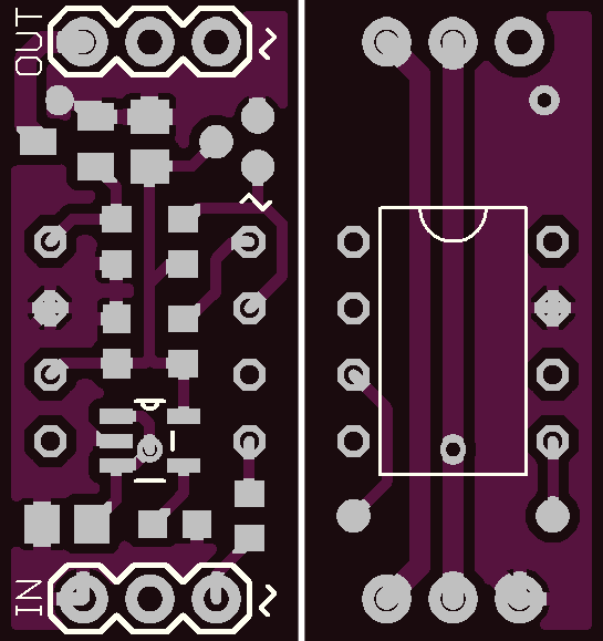
The board measures 0.45x0.95 inch. Below a render of the top and bottom.
The firmware can be found in the firmware/ folder. It compiles fine with the GCC ARM Embedded toolchain. Just run make.
In the contrib folder contains some tools to test the PID controller. First, run python setup.py build_ext --inplace to build a Python wrapper for the exact same PID controller in the firmware. This requires Cython to be available.
See the LICENSE file (MIT license).
This software makes use of other software. Please see firmware/README.md for more information.