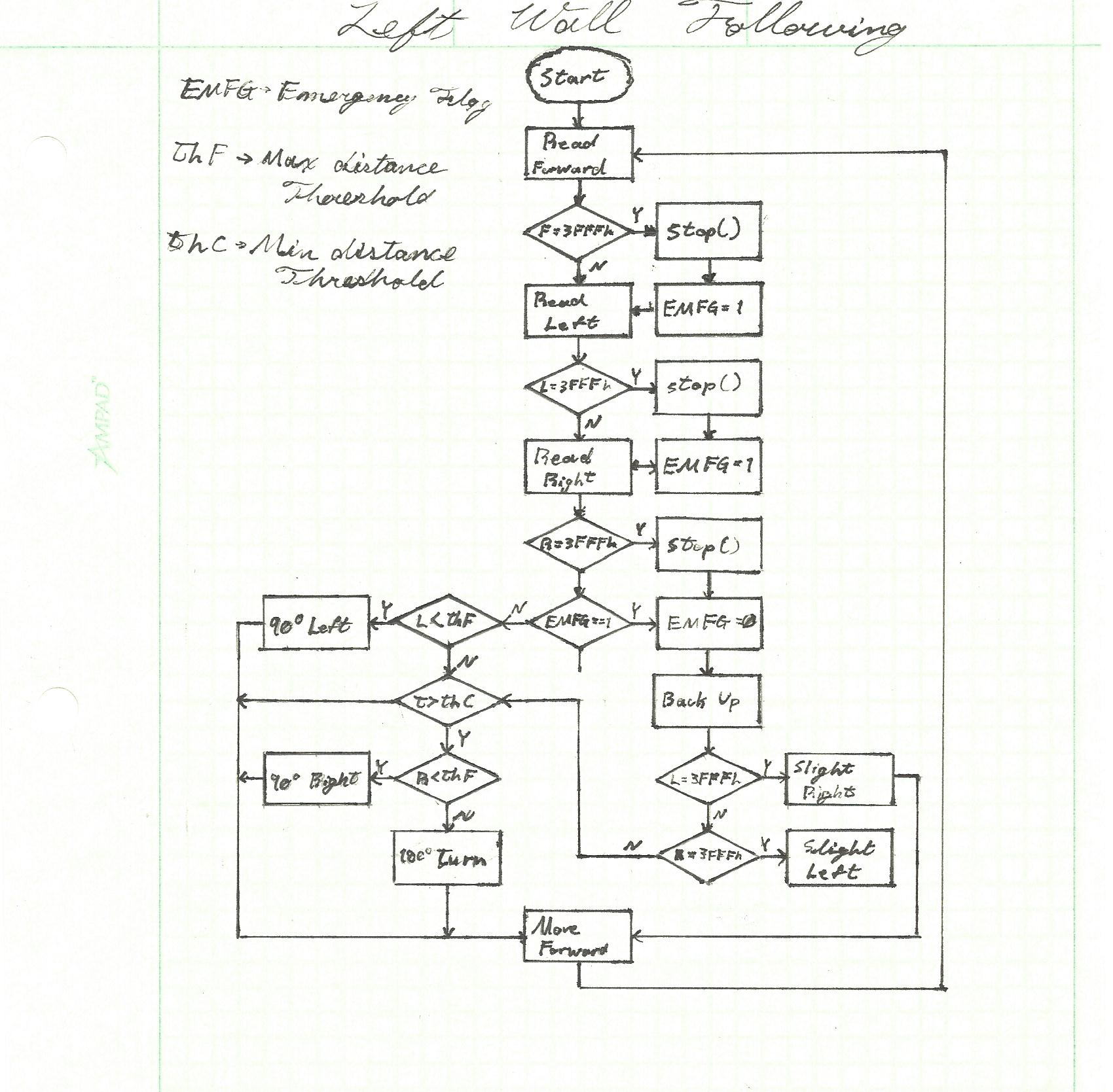
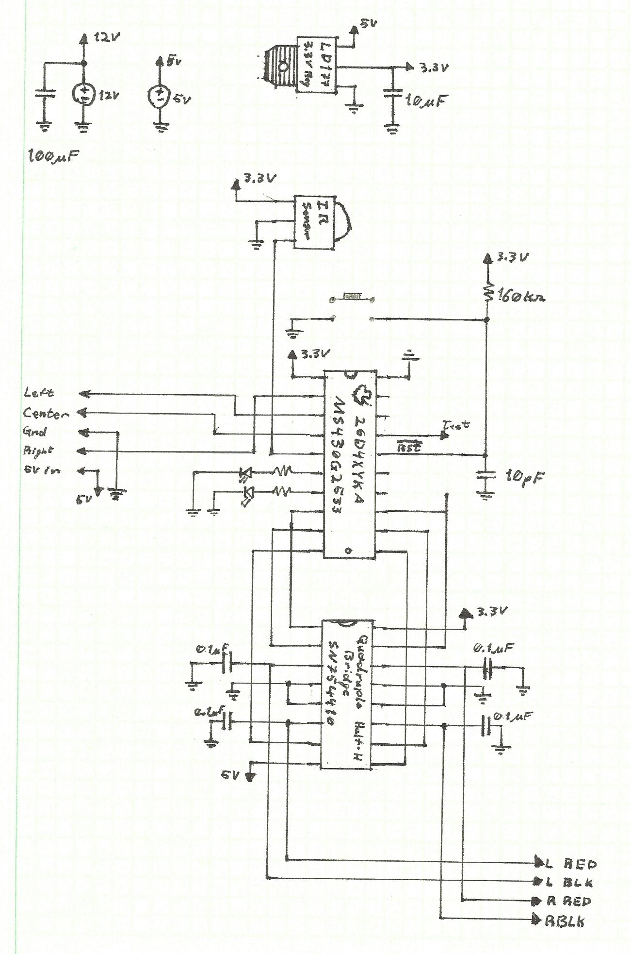
Most of the pre-lab work for this project was tackeled in that of lab 7. It included the hardware layout which was used in this lab, as well as a basic left wall following algorithm. Specific values for the sensor readings could be approximated from the calibration preformed in that lab aswell. A basic flowchart (admittantly created for lab 7) outlining a basic wall following algorithm is shown below in addition to the wiring diagram used both for this lab and lab 78.
Although the circuit did not need to be changed, it was deemed advantagous to point the sensors at 90 degrees from one another to allow the robot to see the walls better. No other changes were made to the robot.
The softeware design was completed sequentially, allowing for systematic (albeit slow) calibration of the robots movement and sensors. While not initially used, the LEDs were initialized and used to indicate which action the robot was performing in response to what it read.
The first aspect of functionality was moving foward and stopping once encountering and barrier. This functionality only used the front sensor to check when when the robot was closer than about 4.5 inches then to stop cold. Movement was accomplished in 0.35 second bursts after each round of read operations at which point the motors would stop as the sensors took in their surroundings. Origionally set to only 1 or 2 reads per cycle, the buffer filling operation was actually outpaced by the robot's movement. While the robot would eventually see the barrier, it was only after ramming head-long into it. The read operaton was then modified to refill the entire buffer (8 cycles) between movement cycles.
This funciton was used to find a rough calibration point for both wheels moving forward. (The left wheel seems to have been full of hair at one point and doesn't work all that well).
The first left wall following algorithm was limited to keeping the robot following along a straight barrier. Because the motors were inconsistnet a scheem for dynamic motor control was implemented where the wheel speeds would be dynamically set as the robot approached closer to or farther from the wall, say a 5% increase or decrease in the duty cycle for the right wheel depending on certain thresholds.
Once a preliminary set of range values for wall following were emperically derrived from tests, a left turn was set in place. This turn would have to navigate around left turning corners and requried following an ark about the corner. A set of wheel speeds were then emperically derrived to provide a good arking turn about any given corner.
During tests with corner turn, it was realized that the dynamic control agorithm made the robot's motion too unstable. In effect, it took time to undo any correction to the wheel speeds and so the robot could not move back to a stable forward fast enough. The next solution was to use static speed correction values to make the correcting adjustiments to the wheels. This method produced much more stable motion in the robot.
Also durring this phase it was discovered that the IR signals would often leave one sensor, bounce off a wall, then interfere with the read of another sensor. This was observed when the robot would go into stop mode while adjascent to a right wall. A 1 ms delay was then added between the sensor reads, and while it did slow down the code, it also prevented the signal interference impeding on the robot's progress.
Up until this point the robot would stop once it reached a wall. However, the arking motion often caused the robot to loop around, hit a wall and stop. The right turn was then designed to adapt to these wall collisions. If the robot does not see a left turn and subsequently runs into a wall , it means that a right turn might be available. The robot then makes a 90 degree right tank turn (wheels move in opposite directions), sees if the coast is clear, then continues moving forward.
Without using the right sensor and just the left wall and right turn functions, the robot was able to make one brief (and undocumented) complete run through the a functionality maze.
After various steps calibrating the wheel duty cycles and movement times for each turn, it was realized that slowing down/shortening the runtime variable for routine moves would add robustness to the code and stability to the robot's movement by sampling the sensors more often. This ended up being the key to stable A functionality as the robot became less likely to run into a wall before sampling.
The robot was only able to complete the maze in one direction. My best guess is that the shadows and lighting changed betwixt the two directions and that was complicating the sensor readings.
C2C Park indicated that pauses between sensor reads helped cut down on interference between each read.