Nun-radio is a Wii Nuncuck based RC transmitter. Something that let's you control 4 channels with a single hand. A full-featured, single-stick ergonomic radio, that's especially handy for multi-hour sessions soaring on the slopes.
Features
- Reading from nunchucks
- Sending data to Frsky's DIY radio module (or any ppm radio)
- Reading telemetry from FrSky's DIY radio module (2-way protocol)
- Remaining battery/rssi display
- Audible alarm for low battery and low signal strength
- Expo and dual rates
- A screen display with model and setup information
- Multiple models with selection
- Persistent trim
- Switching between mode1/mode2 (elevator/aileron via tilt or via joystick)
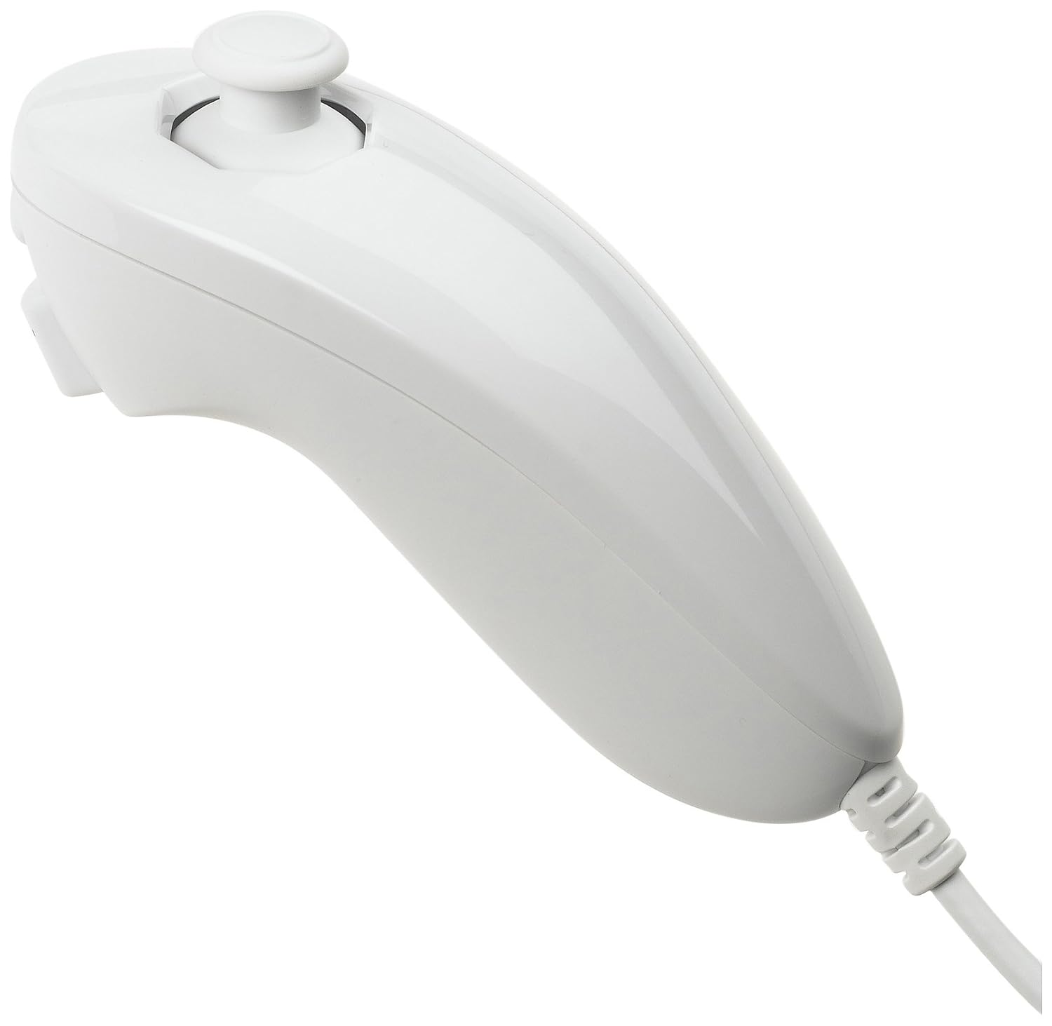
The only control input is the Wii Nunchuck. I've tested with wireless and wired models, the original nintendo one as well as cheap knockoffs. The all seem to work just fine.
By default tilt left/right controls roll. Tilt forward/backwards controls pitch. Joystick left/right is for rudder, up/down is for throttle.
You can also flip what joystick and tilt controls. That's achieved by hitting the Z button.
Calibration can be entered by moving the joystick full right and hitting both C and Z buttons at the same time. The screen will show instructions on how to perform the calibration.
Trim can be set by holding a certain position on the joystick and with tilt and hitting the C button. The current position will immediately become the new center. Trim can be performed any number of time, each time the "new" center will be relative to the "current" center. This way you can trim each axis one by one.
Saving the current trim is done by holding the joystick full left and hitting both C and Z.
You can switch between high and low rates by pressing both Z and C button simultaneously in flight while the stick is not at an extreme (e.g.: center position). A high pitched tone will indicate high rates are active, a low pitched tone indicates the low rates are active.
You can choose pre-programmed models by holding the joystick full up or down and hitting both C and Z. This will page through all available models.
Models are created in the code. ModelRegistry.h has all the models. The important bits of model creation are:
- Model name
- Number of inputs used
- Number of channels used
- Expo for each channel (Percentage, 0% is no expo)
- Low and high rates for each channel
- Mix matrix (see below)
Channel mixing is achieved by setting up the mix matrix. If you configured n inputs and m channels to be used, the mix matrix is a nxm matrix that will be multiplied to the input vector to produce the channel outputs.
So if I is your input vector (by default (rudder, elevator, throttle, aileron)) and A a 2 x 4 matrix: A*I will be what's sent to the model.
Let's say you have a 2 channel model with elevons. You've configured 4 inputs and 2 channels. The matrix you want to use is this:
0 1 0  1
0 1 0 -1
That will add up aileron and elevator for channel 1 and add up the inverse of the aileron and elevator for channel two.
(The actual values for the matrix are given as "PERCENT_TO_BYTE(x)" where x is the percentage of the input value you want to take. This is done for code size reasons.)
If you're glider has 4 channels: Two for ailerons, one elevator and one rudder, your matrix would likely look like:
1 0 0  0
0 1 0  0
0 0 0  1
0 0 0 -1
(Same comment about actual matrix values applies)
Expo is set as a percentage. If the expo percentage is "a" and the control input is "x" the formula used is:
(a/100) * x^3 + (1 - a/100) * x
High and low rates are applied as a last step before the channel values are sent to the servos. If "a" is the percentage of the high or low rate the formula is:
(a/100) * x
You'll need the following things to build the radio.
The controller. I like the Nyko Kama for Wii, but any cheap Nunchuck will work.
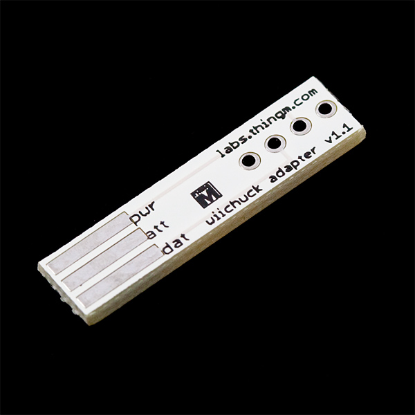
This little board let's you read your nunchuck from Arduino without having to destroy it. Just connect the nunchuck to the board and done.
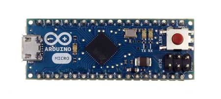
The heart of the radio. I'm using the Arduino Micro, but any Arduino will work (UNO, pro, etc).
The good folks at FrSky have a radio module that is perfect for projects like this. It's small cheap and let's you establish 2 way comm with any FrSky receiver. That means easy transmission of signal as well as reading of telemetry info via Arduino.

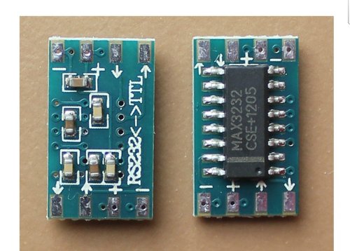
This little board let's you read the telemetry output of the FrSky DHT DIY radio directly with the Arduino hardware serial port. It converts the RS232 signal to TTL (inverts levels, adjusts voltages).
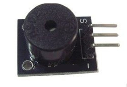
Simple piezo speaker to sound alerts for low radio battery, low airplane battery or low signal strength.
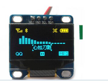
You'll need a small screen for model selection, visual telemetry, checking on battery, and visualizing input and output.
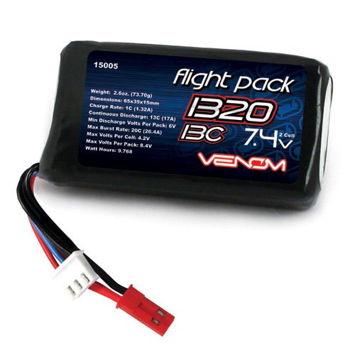
You need something to power the radio. I'm using a 2S lipo.
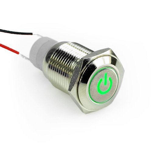
Any 2 position switch to turn the radio on and off. I'm using this latching button although it's expensive and too big. I'm sure you can find better.
You'll also need to wire all this stuff together. Breadboard, prototype boards, soldering wires. There's plenty of options.
Below is how you wire the radio.
- Battery goes through switch to VIN on the Arduino. GND needs to be connected to Batter ground. Speaker, MAX3232, Telemetry, nunchuck, screen take 5V, the transmitter takes direct input from the batter. The battery in the picture is 3.7V but should read 7.4V (2S Lipo)
- Both screen and wii nunchuck are I2C devices. They need to be connected to the respective I2C ports on the Arduino.
- There's a 100k/10k pair of resistors connected to Analog port 0. That's used to read the battery voltage.
- The speaker is connected to digital pin 13. That means on board LED and Speaker are coupled. That can be annoying when uploading new code. You might want to use a different pin.
- The FrSky DHT's PPM port is connected to digital pin 5. The transmitting side will take the battery voltage.
- The FrSky Telemetry ports have to receive 5V input. The TX port on the FrSky needs to be routed through the MAX3232 to the RX port of the arduino.

The build is done via: https://github.com/sudar/Arduino-Makefile
You'll need to head over there to get the setup instructions. Please note: I had to use the older Arduino 1.0.5 to make the Makefile works. This might change in future.
You'll have to go through the Makefile and adjust it to your environment. There's paths for AVR, where you checked out the code, you need to choose the right board you're using etc.
After that, you just need to plug in your arduino and run:
make upload
And voila. The radio is working.
Lots of 'borrowed' code in this project. Here's where the pieces are from:
- RCEncoder was lifted from the Arduino forums: http://www.arduino.cc/cgi-bin/yabb2/YaBB.pl?num=1243998214
- Adafruit_* code is form here: https://github.com/adafruit (both the graphics and the ssd1306)
- WiiChuck from the Arduino playground: http://playground.arduino.cc/Main/WiiChuckClass