This project was developed for the HAPR module final assessment. The team was composed of myself (Zisu Andrei-Costin), Michael Mokrysz and Alex Oyston. The task was to build a digital guitar amplifier and effects processor.
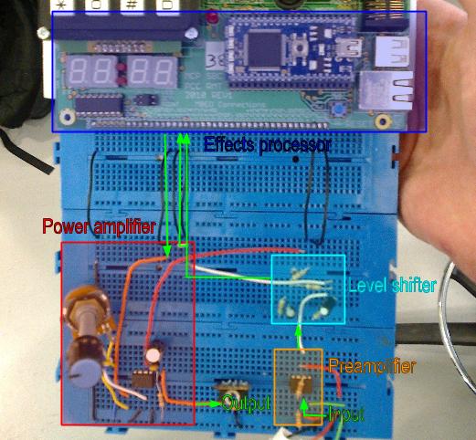
Above you can see the electronics blocks to get the signal from an electric guitar to the board and out of the board to headphones or speakers. The platform is a motherboard and pin-out for a NXP LPC 1768 microcontroller power by an ARM Cortex M3. However, all the mother-board specific code has been removed.
- Use
make clean && make && make installto install the firmware, then reset the microcontroller to boot. - Assumptions:
- The 0 amplitude voltage level is 2V.
- The minimum input value is 0.7V and the maximum output value is 3.3V.
- Uses the Cortex Microcontroller Software Interface Standard (CMSIS) library.
- Uses the Sourcery G++ Lite Edition for ARM libc implementation, which is, unfortunately no longer available. Information about porting is available below.
The firmware, is based on multiple streams representing sound waves implemented as buffers. Each stream is transformed by a corresponding filter, a self-contained (possibly containing internal state), well-defined mathematical function o. Each filter can have two outputs and up to two inputs (allows for multiplexing and splitting).
The filters are classified into:
- generators, which take no input, but generate an output, e.g. input filter, sine wave generator, and could include filters which read from flash memory;
- consumers, which take an input but generate no output, e.g. the output filter, and could include filters which save to flash memory;
- passive, which move data from the input buffer to the output buffers without altering it, e.g. the passthrough filter;
- effects, which read the input buffer at different points in time and perform operations to determine what value to put in the output buffers, e.g. delay, min, max, distort, reverb, tremolo, flange, compressors or noise reduction.
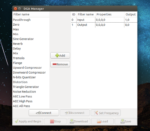
As the effects processor boots up, it initializes into the “passthrough” mode, which is implemented using only an input and an output filter. The user can then, using either the GUI or even a serial communication terminal, describe the filter list the board should run.
On such a resource-limited system like the LPC 1768, with only 64 kB RAM, finding space for all the necessary buffers proved to be difficult. To make matters worse, when using the version of malloc contained by the libc runtime library, we found that the memory got fragmented fairly quickly. To work around this problem, we developed our own memory allocation system.
The system uses two statically allocated integer arrays as a memory pool. The first one is conveniently included at the start of the program file to trick the linker into placing it at the top of the .bss segment of the binary file. The second pool is manually placed into the block of memory reserved for Ethernet and USB, since those peripherals were not used.
The reason why we sought after allocating the first buffer at the start of the program file is that the flash memory programming driver requires it's buffers to be mapped in the first 16KB block of memory. This system conveniently solves the problem, without resorting to any special tricks.
Using the custom allocation system, we found that we can store up to 22000 samples in memory at the same time, as opposed to only up to 6000 using the previous solution. Moreover, as, in the effects processor’s life-cycle, allocation only ever happens after the memory is freed in its entirety, where the previous system did not guarantee fragmentation-free allocation, the new system allocates memory at consecutive places in the pool.
The logic is separated from hardware-dependant code through drivers. These are implemented in the following files:
adc.calloc.cdac.ciap.c(flash memory access)serial.ctimer.c
- running on Python 2.7, depends on pyGTK and pySerial.
- Assumptions:
- You are running on a *nix system and the board's serial terminal can be found at
/dev/ttyACM0. - pyGTK has glade file support.
- You are running on a *nix system and the board's serial terminal can be found at
- Use
python gui.pyto run. - Value range for filter parameters: [0, 100]
- Each filter can have at most 4 parameters, and at most 2 outputs.
- Block id values take integer values in the range [0, 9]
- Using a high sampling rate will prevent the board from reading/writing to serial.